Most embedded projects live in a toolchain, but real systems rarely do. They often combine multiple microcontrollers, each developed where engineers feel most comfortable.
This demo shows how these environments can be assembled into a connected system: a smart greenhouse roof that opens automatically when rain is detected or can be opened/closed manually by interacting with a touch panel.
The project brings together multiple development environments, each with a specific role in sensing, decision-making and control, all communicating seamlessly over UART. In the following sections we will walk through how each part was built: configuring fluid detection in MPLAB® Data Visualizer, touch control in MPLAB for VS Code, and system coordination with Zephyr RTOS.
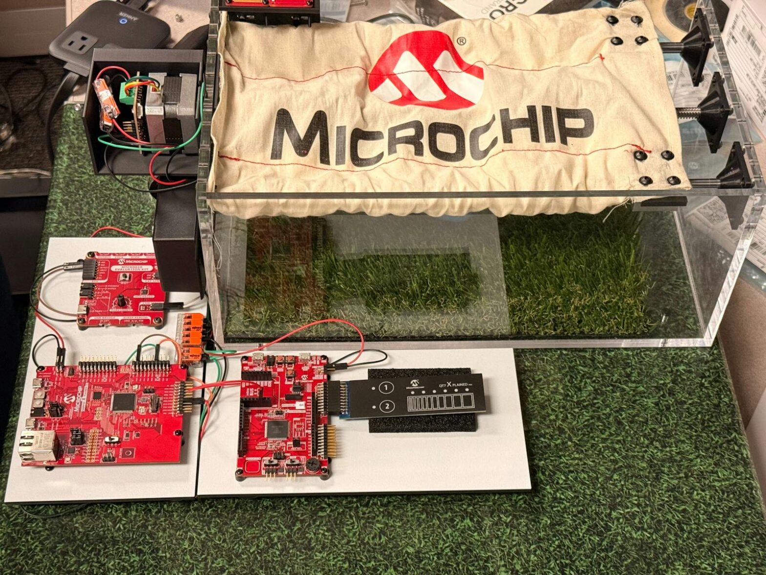
Rain controlled greenhouse automation hardware
At the center of the system is the SAM E54, which runs Zephyr RTOS as the main controller.
It receives input from two sources:
- MTCH9010: Rain detected →open roof
- PIC32CM GC00: Touch slider or buttons → manual open/close
The SAM E54 processes each event, decides what action to take, and sends a UART command to the AVR® EB Smart Stepper Motor Board, which drives the motor to move the roof.
Toolchain overview of rain-triggered greenhouse automation
Each part of the greenhouse demo was developed using a different toolchain. In this section, you'll learn how each part was built and how the development environment shaped its role in the system.
MTCH9010 – Liquid Detection Setup in MPLAB® Data Visualizer
The MTCH9010 is a hardware-based liquid detection IC that detects both conductive and capacitive liquids. It is a standalone device that requires no firmware and outputs a digital signal when liquid is detected. It can be adapted to different detection conditions or performance requirements through configurable parameters such as detection thresholds and rest times. Because detection is done entirely in hardware, it responds instantly and uses very little power – ideal for always-on systems like this smart greenhouse roof.
You can configure the MTCH9010 in different ways:
- Onboard slide switches – the easiest way to adjust sensitivity and detection behavior directly on the board.
- UART Terminal – allows configuration from a PC with serial commands via USB, useful for precise tuning and testing.
- MPLAB® Data Visualizer MTCH9010 Extension – a graphical tool that provides real-time visibility into sensor data and allows you to customize settings through a user-friendly interface.
If you want to explore these configuration methods in more detail, you can find them here MTCH9010 Getting Started And MPLAB® MTCH9010 Plugin User Guide goes through each option step by step.
For this demo, the Data Visualizer Extension was used to optimize detection and verify stable performance. Once configured, the MTCH9010 outputs a digital signal to the SAM E54, which interprets it as a “Rain Detected” event and closes the roof.
Below is a GIF showing the MTCH9010 Data Visualizer Extension in action, along with a labeled diagram of the MTCH9010 Evaluation Kit for reference.
MPLAB® Data Visualizer MTCH9010 extension
PIC32CM GC00 – Touch interface configuration in MPLAB® Tools for VS Code
The PIC32CM GC00 (Arm® Cortex®-M23) handles manual user control via a QT7 XPLAINED PRO expansion kit. Using the MPLAB Code Configurator for VS Code and the MPLAB® Touch Library, the device's Peripheral Touch Controller (PTC) can be fully configured through a visual interface without the need for low-level register coding.
PIC32CMGC00 & QT7 XPLAINED PRO
The MPLAB® Tools extension for VS Code lets you do everything from one workspace: open MCC, optimize touch channels, view signal graphs, and generate code directly in your project. Shown below is the Touch Library configuration window, where touch channels and thresholds are defined before code generation.
The MPLAB® Tools extension for VS Code lets you do everything from one workspace: open MCC, optimize touch channels, view signal graphs, program and debug the device, and generate code directly in your project. Shown below is the Touch Library configuration window, where touch channels and thresholds are defined before code generation.
MPLAB extensions for VS Code
Once generated, the firmware uses the library's functions to recognize key and slider inputs and send UART frames to the SAM E54. The SAM E54 interprets these frames and passes a command via UART to the AVR® EB stepper controller, which rotates the motor to move the roof according to the UART message.
Each button and slider “zone” corresponds to a specific UART value, allowing for smooth manual roof control.
Below is a snippet from the firmware showing how button and slider inputs map to UART frames:
// Button zones → UART mapping
uint8_t Mess1[] = {0xA0, 0x01, 0x5A}; // CLOSE
uint8_t Mess2[] = {0xA0, 0x01, 0x00}; // OPENif (curr_button0_pressed && !prev_button0_pressed) {
SERCOM2_USART_Write(Mess1, sizeof(Mess1));
}
if (curr_button4_pressed && !prev_button4_pressed) {
SERCOM2_USART_Write(Mess2, sizeof(Mess2));
}
// Slider zones → UART mapping
uint8_t Slider6[] = {0xA0,0x01,0x5A};
uint8_t Slider5[] = {0xA0,0x01,0x45};
uint8_t Slider4[] = {0xA0,0x01,0x36};
uint8_t Slider3[] = {0xA0,0x01,0x2D};
uint8_t Slider2[] = {0xA0,0x01,0x15};
uint8_t Slider1[] = {0xA0,0x01,0x00};
switch (curr_slider_zone) {
case 6: SERCOM2_USART_Write(Slider6, sizeof(Slider6)); break;
case 5: SERCOM2_USART_Write(Slider5, sizeof(Slider5)); break;
case 4: SERCOM2_USART_Write(Slider4, sizeof(Slider4)); break;
case 3: SERCOM2_USART_Write(Slider3, sizeof(Slider3)); break;
case 2: SERCOM2_USART_Write(Slider2, sizeof(Slider2)); break;
case 1: SERCOM2_USART_Write(Slider1, sizeof(Slider1)); break;
default: break; // Not touched
}
The PIC32CM GC00 processes touch locally, sends frames to the SAM E54 and the SAM E54 routes motor commands to the AVR EB, a clean MCC + VS Code workflow for fast, reliable prototyping
SAM E54 – System coordination in Zephyr RTOS
The SAM E54 acts as the main controller and runs Zephyr RTOS to coordinate communication between MTCH9010, PIC32CM GC00 and the AVR® EB Stepper Board. It waits for a detection signal from MTCH9010 and UART frames from PIC32CM GC00, decides the corresponding system action (open or close), and sends a corresponding UART command to the AVR EB stepper board to move the roof.
Zephyr simplifies this by separating hardware mapping. The PIC32CM GC00 processes touches locally, sends frames to the SAM E54, and the SAM E54 processes the data and passes motor commands from the application logic to the AVR EB. The app_board.overlay defines how peripherals are connected to the SAM E54 by mapping GPIO inputs, UART interfaces and LED outputs, while main.c manages all control logic.
Rain-triggered greenhouse automation software overview
Below you can see some example definitions from our app_board.overlay for this project:
/* Detect input from MTCH9010 */
mtch9010_signals {
    compatible = "gpio-keys";
    mtch9010_detect: gpio {
        gpios = ;
        label = "MTCH9010 Detect";
    };
};/* UART channel for GC00 data */
&sercom1 {
    status = "okay";
    compatible = "microchip,sercom-g1-uart";
    current-speed = ;
};
Microchip's Zephyr board files already define the common peripherals (SERCOM UARTs, GPIOs, etc.), so the project overlay simply extends this configuration by specifying where application-specific peripherals are located, what drivers they use, and any parameters that need to be set. Zephyr's Devicetree system then automatically takes care of applying these pin assignments and connections in the background.
In main.c, these overlay-defined nodes are accessed directly using the labels assigned in Devicetree:
#define WATER_NODE DT_NODELABEL(mtch9010_detect)
static const struct gpio_dt_spec water_in = GPIO_DT_SPEC_GET(WATER_NODE, gpios);static const struct device *const uart_in  = DEVICE_DT_GET(DT_NODELABEL(sercom1));
static const struct device *const uart_out = DEVICE_DT_GET(DT_NODELABEL(sercom5));
The main loop continuously monitors the inputs and sends commands to the AVR EB stepper board:
if (water_is_active()) {
    uart_out_frame(VAL_CLOSED);  // Close roof on rain detect
} else {
    commit_slider_if_idle();     // Manual slider input from GC00
}
Together, the overlay defines the connections while my code in main.c defines the behavior, creating a clean, maintainable structure that cleanly separates configuration from logic.
️AVR® EB Stepper Motor Controller – Motor Movement in MPLAB® X IDE
The AVR® EB serves as an actuator for this system, translating UART commands from the SAM E54 into precise movements. It is based on Microchip's Smart Stepper Motor Controller reference design, which leverages the AVR® EB family of MCUs to generate the required waveforms for step, half-step or microstep steps.
Intelligent stepper motor driver reference design
Since the waveform generation is handled by the AVR EB MCU itself, the motor can run independently without the need for real-time control by the SAM E54. This enables smooth and reliable movement even when other parts of the system are busy.
The firmware development was carried out in MPLAB® X IDE, based on a motor controller Code example which uses the AVR® EB stepper motor reference design. The sample source code available on MPLAB® Discover was reused and adapted for this demo. When the SAM E54 sends a UART frame corresponding to a open or close The AVR-EB interprets the message and moves the motor to the target position.
While the circuit board attached to the motor is a custom reference design, this functional block can be replicated as follows:
- Multi-Phase Power Board (MPPB) – EV35Z86A
- AVR EB Curiosity Nano Adapter – EV88N31A
- AVR EB Curiosity Nano – EV73J36A
Together, these boards replicate the same level of control as in the demo and provide a flexible platform for stepper motor development. The firmware image for this setup is available Here.
Bringing everything togetherThis project demonstrates how multiple development environments can work in harmony to create a single, intelligent application. Each device is designed with the tools best suited to its task:
- MTCH9010 – Configured with the MPLAB® Data Visualizer Extension for real-time tuning and visualization.
- PIC32CM GC00 – Developed in MPLAB® Tools for VS Code using MCC and the Microchip Touch Libraries for a responsive, moisture-tolerant touch interface.
- SAM E54 – Runs Zephyr RTOS and handles coordination, logic and communication between all system components.
- AVR® EB – Powered by microchip motor control libraries to control the stepper motor that moves the greenhouse roof.
More than just a demo, this project reflects Microchip's ongoing commitment to enabling developers to work within the toolchain of their choice. Whether you prefer MPLAB X, VS Code, or Zephyr, our goal is to make it easier to bring these ecosystems together in a seamless, connected design.